C++ code generation from PCSSP
This document describes the method and policies in generating real-time C++ code for deployment of PCSSP modules on the ITER PCS. This method is not final and is the result of heavy prototyping activities with help from both General Atomics and CREATE.
Why code generation?
The control engineering domain has transitioned from heuristic, iterative control development methods into model-based design (MBD). In the latter, dynamic models of the to-be-controlled system are developed and subsequently used to tune/synthesize and assess (feedback) controllers. While the development of a dynamic model requires time, the model-based design paradigm, with a system model at the heart of the development, has several advantages:
MBD opens the pathway to advanced control techniques like H-infinity synthesis, robust control, learning control, and predictive control.
MBD reduces the strain on controller tuning on the real device/experiment since most of the design can be done offline
MBD allows formal assessment of the control against requirements and safety limits
MBD allows for much more and faster iterations of control solutions, since they can be tested on the model
A large caveat of MBD has always been the deployment (implementation) of the designed controller on the target system, which still required manual coding. This, however, has been largely overcome by process automation in the form of code generation. Instead of writing production code by hand, the code is generated directly from the model, such that the model forms a bridge between design teams and software engineers. Code generation has therefore enabled much faster and safer deployment of controllers on target hardware. It is for this reason that MBD with code generation has always been one of the desired application domains of PCSSP, and it is the main reason why PCSSP is based on Simulink software, being the leading authority on model-based design with code generation.
The MBD workflow
The figure below schematically shows the steps from design in Simulink to implementation on the target hardware. Clearly, this is an iterative process, since most often the controller algorithms need adjusting after their initial deployment.
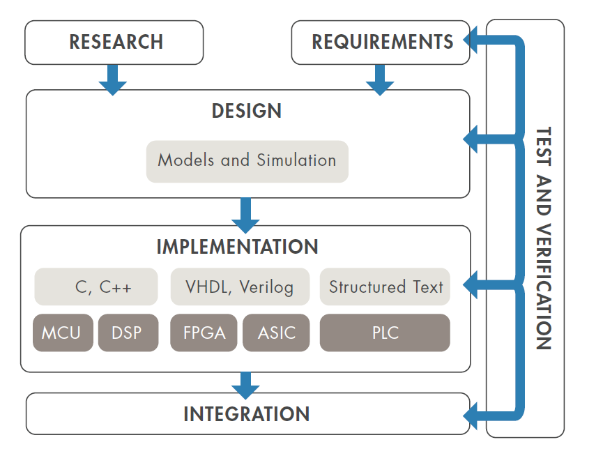
Model-based design workflow (source: Simulink white paper on MBD)
Requirements for RTF production code
The relative ease of code generation within a model-based design and testing workflow has led application engineers to repeat the steps of code generation and re-compilation often in the integration step. However, for ITER we cannot recompile often given the stringent reviews and hardware tests for production code that are required. Instead, we aim to:
Generate human-readable code: few inline/hardcoded parameters, clear signal, parameter, and function names
Introduce flexibility in the configuration of the generated code
Have ample tunable parameters allowing tuning of controllers and models without re-compilation
Generate code on the functional block level and not the computational node level: for example a single controller instead of the full real-time thread.
These requirements actually push the limits of current code generation capabilities. The following therefore has to be seen as a prototyping activity which will improve and mature in the near future.
Requirements for PCSSP modules
An introduction to code generation is provided here. You can generate code from most Matlab code (embedded in Simulink via the Matlab function block) and most Simulink blocks. The basic process is shown in the figure below.
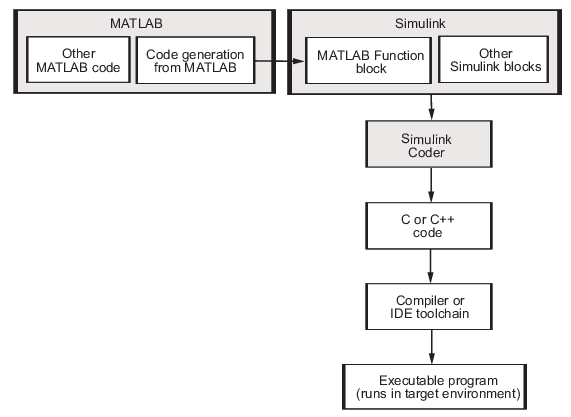
Flow chart demonstrating the waterfall approach to code generation. In reality this is an iterative process (next figure)

Workflow for code generation from Matlab and Simulink (Source)
The PCSSP framework aims to support the code generation of modules by providing methods and functionalities for the various class instances for different levels in the hierarchy. In principle, code can be generated on the pcssp-module and pcssp-wrapper levels. The higher layers in the hierarchy simply loop over the registered modules and generate their code. All generated code is automatically put in the gencodes directory in the root of the repository. Subdirectories therein contain code for individual modules. The approach to generate code for your module is as follows:
determine which parameters need to be tunable and migrate them to the tunable parameter definition scripts
Make sure you have no continuous states and other blocks in the model that are not supported for code generation. This is automatically verified by launching the module test class with the
iscodegenflag switched on.Add bus objects for input and output ports. This allows the generated code to preserve the signal naming and structure, and better control the type checking of the signals contained in the port. Make sure to add a Description field to each bus object which is picked up by RTF later.
Make sure you have a Simulink
configurationReferencelinked to your model. Check the how-to here: Referencing Simulink ConfigurationsAfter init/setup, call the
pcssp_module.build()method to generate code using the RTF recommended settings. The code is stored in the gencodes directory in the repo’s root.call the
pcssp_module.write_xml()method. This automatically generates the XML RTF application description listing the tunable parameters and FunctionBlock I/O.
Examples of this workflow are provided in the templates/ directory. The most elaborate example is the KMAG module, which also supplies a full baseline comparison test to make sure the output of the generated code exactly matches the simulink model.
